Robotbit Coding with KittenBlock
Robotbit can be programmed with KittenBlock.
Refer to this page for introduction with Kittenblock: Kittenblock Introduction
Kittenblock Coding

Connect the Micro:bit to your computer with a USB cable.
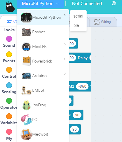
Click select hardware and choose MicroBit Python from the menu.
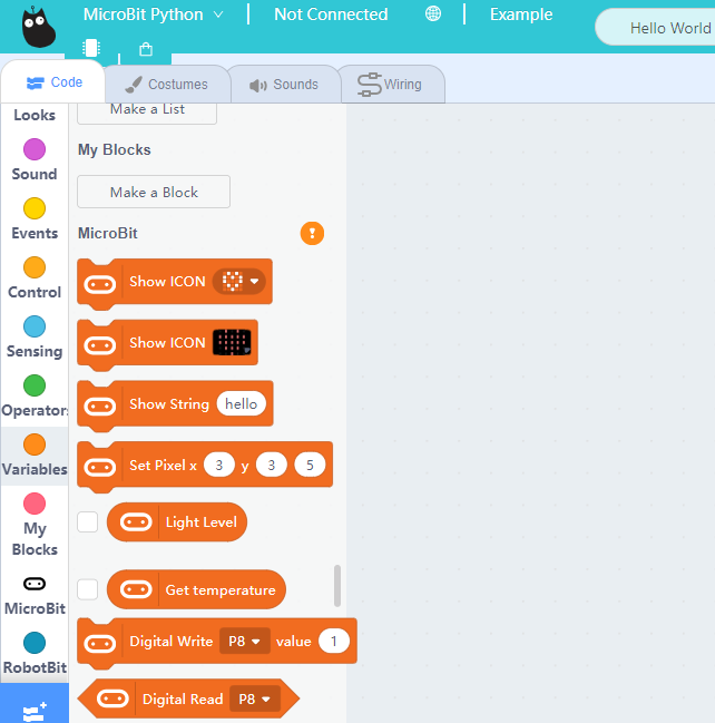
Press this exclamation mark(!).
Click this button to connect the Micro:bit.
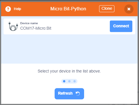
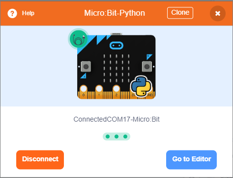
Micro:bit will display a heart icon after connecting to Kittenblock.
If the Micro:bit does not show a heart icon,

The blocks for Robotbit will be added
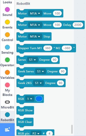
1. Programming Motors
For information about DC motors by Kittenbot, please visit: Kittenbot Actuators
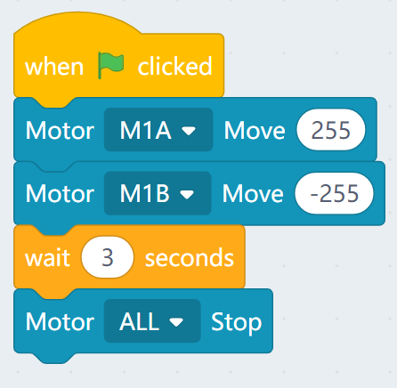
Sample Program:
Connect 2 DC motors to the M1A and M1B port of the Robotbit.
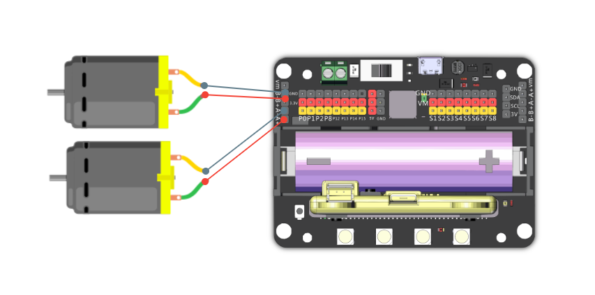
The speed of motor ranges from -255 to 255.
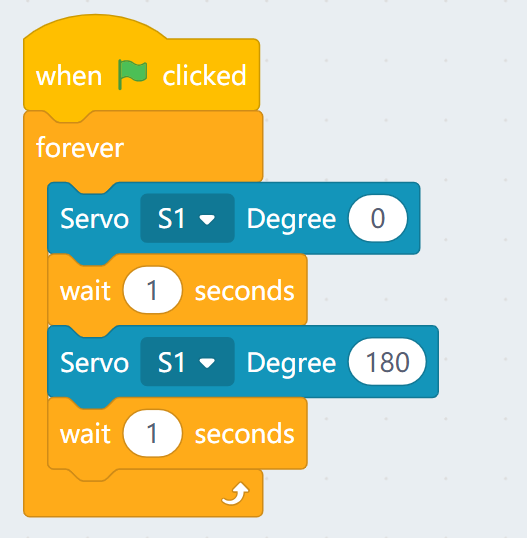
2. Programming Servos
For information about servos by Kittenbot, please visit: Kittenbot Actuators
Sample Program:
Connect a servo to the S1 port of Robotbit.
Connect the orange wire from the servo to the yellow wire of the Robotbit.
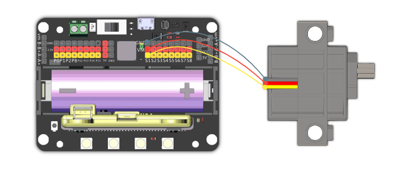
Typical servos have a rotation range of 0-180.
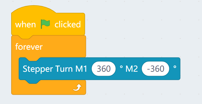
3. Programming Stepper Motors
For information about DC motors by Kittenbot, please visit: Kittenbot Actuators
Sample Program:
Connect Stepper Motors to the M1 and M2 port of the Robotbit, with the red wire connecting to the VM port.
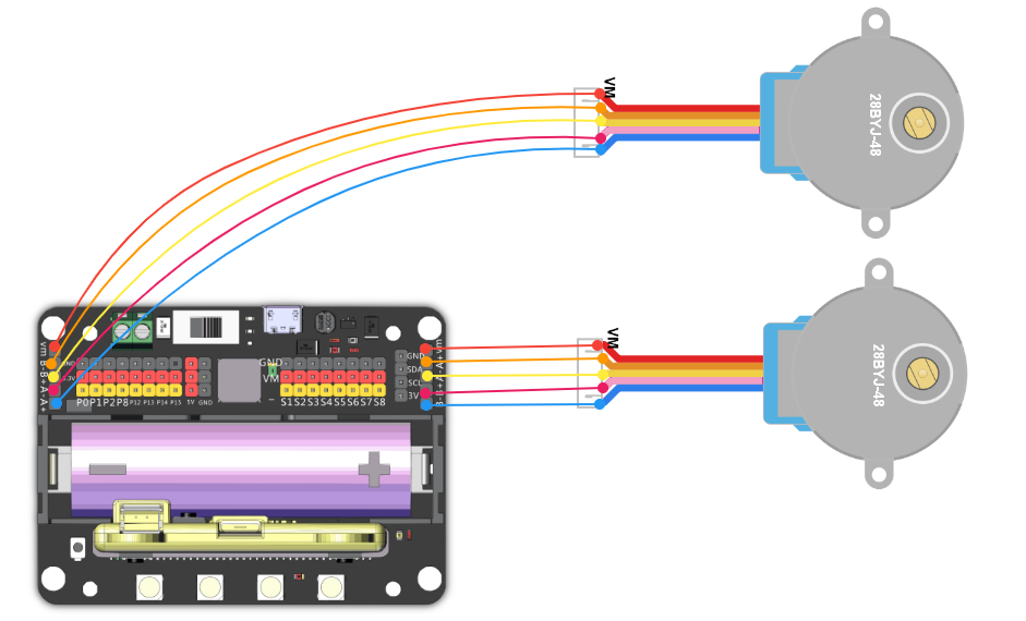
Stepper Motors have a rotation range of -360 to 360.
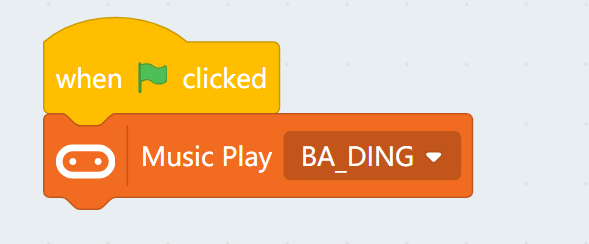
4. Programming the buzzer
Do not remove the buzzer jumper when using the buzzer.
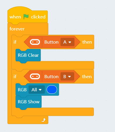
5. Programming the built-in LED strip
Remember to add a "Show" block to display the effect.
5.1 Lighting up all lights
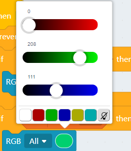
5.2 Customizing color with RGB
RGB value has a range of 0-255.
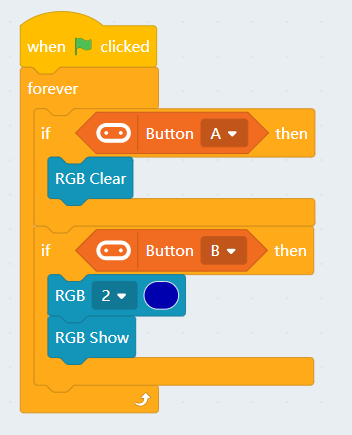
5.3 Lighting up individual lights
The lights are labelled 0-3. (As labelled on the Robotbit)
![]()
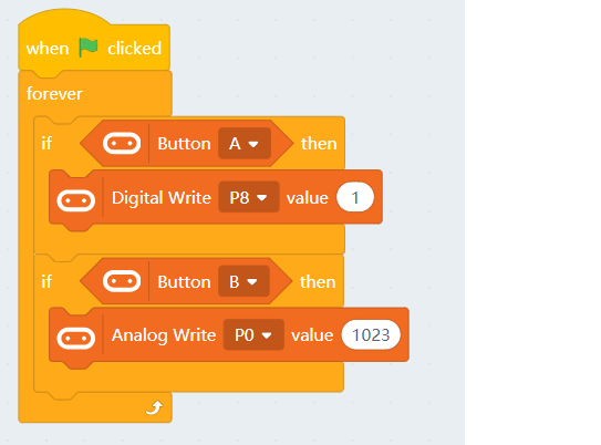
6. Programming the IO Pins
The blocks for the IO pins are found in the menu for Micro:bit.
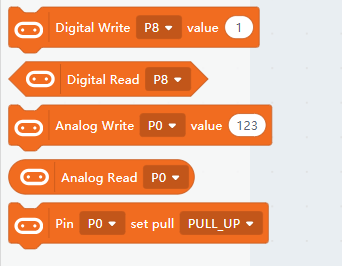
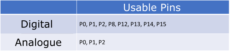
Pin 0-2 can be used as analog pins while P8, P12~P15 can only be used as digital pins.
Analog values have a range of 0 to 1023, digital values have a range of 0 to 1.
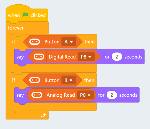
6.1 Reading values from pins
Pin 0 is occupied by the buzzer by default, the jumper should be removed when using this pin.
6.2 Writing values to pins
Pin 0 is occupied by the buzzer by default, the jumper should be removed when using this pin.