Robotbit Coding with MakeCode
Robotbit can be programmed using Microsoft MakeCode.
Makecode Coding

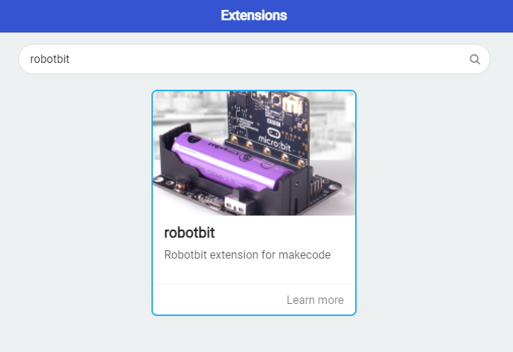
Loading the extension for Robotbit
1. In the extensions page, search for “Robotbit”.
Robotbit and its extension has been officially approved by Microsoft.
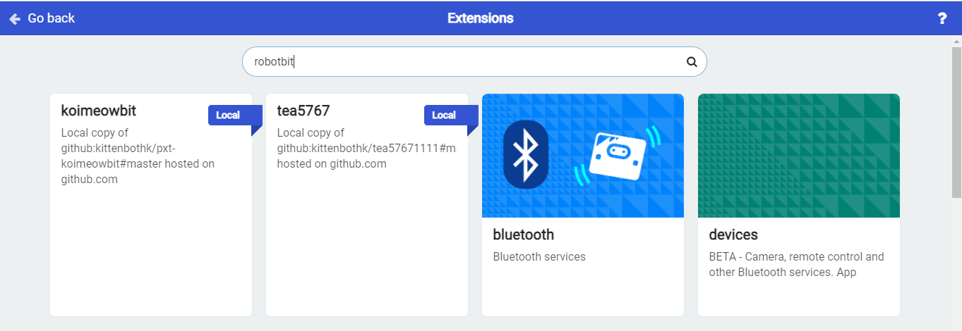
2. In Offline MakeCode by Kittenbot, the Robotbit extension can even be loaded without access to the internet.)
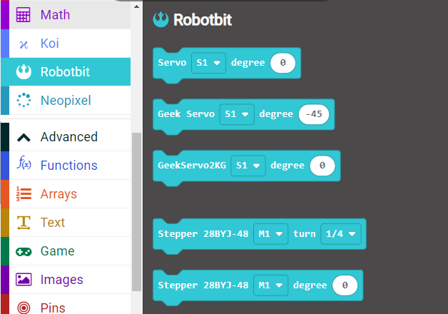
The blocks for Robotbit is added
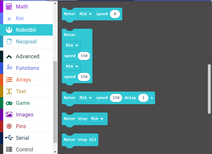
1. Programming Motors
For information about DC motors by Kittenbot, please visit: Kittenbot Actuators
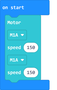
Sample Program:
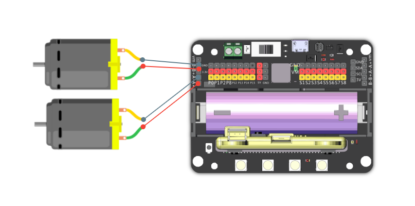
Connect 2 DC motors to the M1A and M1B port of the Robotbit.
The speed of motor ranges from -255 to 255.
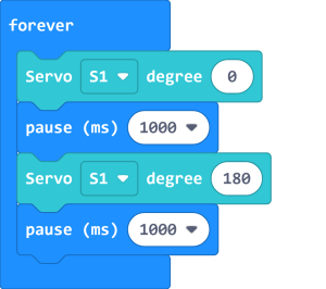
2. Programming Servos
For information about servos by Kittenbot, please visit: Kittenbot Actuators
Sample Program:
Connect a servo to the S1 port of Robotbit.
Connect the orange wire from the servo to the yellow wire of the Robotbit.
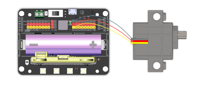
Typical servos have a rotation range of 0-180.
3. Programming Stepper Motors
For information about DC motors by Kittenbot, please visit: Kittenbot Actuators
The programming blocks were designed for Kittenbot's 28BY-48-5V stepper motor, using other motors may result in reduced accuracy.
Sample Program:
Connect Stepper Motors to the M1 and M2 port of the Robotbit, with the red wire connecting to the VM port.
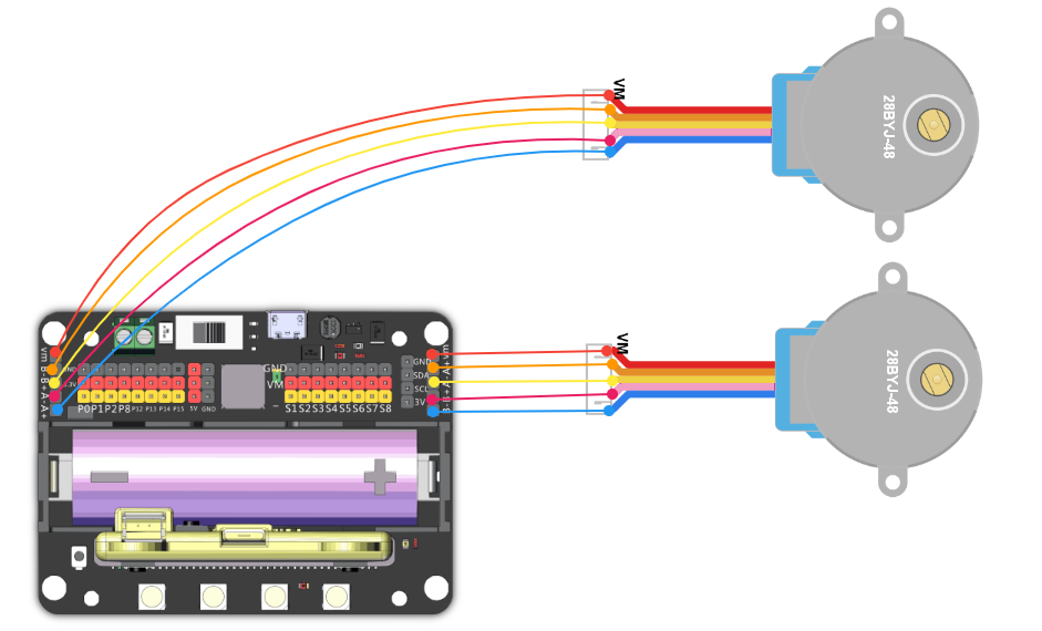
Stepper Motors have a rotation range of -360 to 360.
4. Programming the buzzer
Do not remove the buzzer jumper when using the buzzer.

5. Programming the built-in LED strip
The programming blocks for the LED strip are found in the Neopixel tab.
![]()
Remember to add a "Show" block to display the effect.(Except show color.)
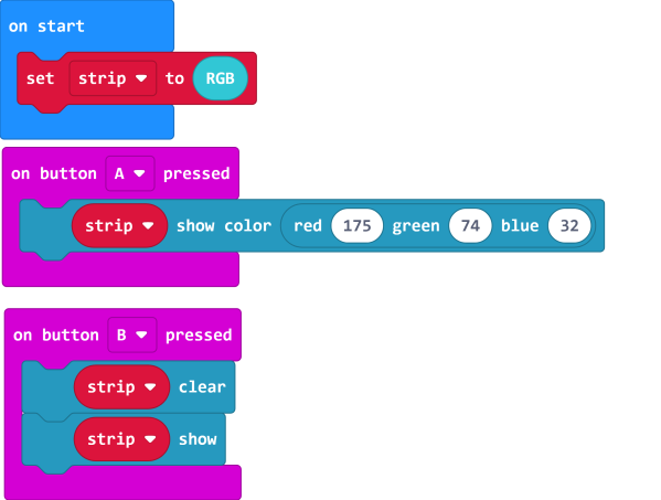
5.1 Lighting up all lights
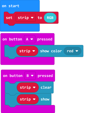
5.2 Customizing color with RGB
RGB value has a range of 0-255.
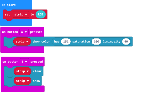
5.3 Customizing color with HSL.
HSL consists of a hue value with the range 0-360, a sturation and brightness value with the range 0-100.
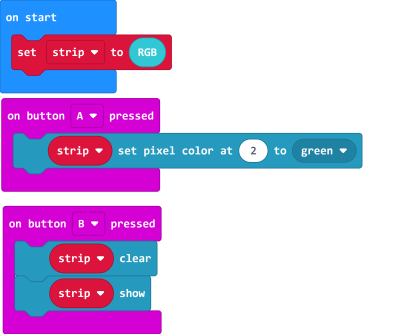
5.4 Lighting up individual lights
The lights are labelled 0-3. (As labelled on the Robotbit)
![]()
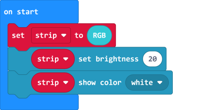
5.5 Adjusting the brightness.
The brightness level has a range of 0-255.
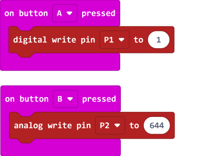
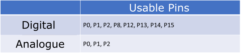
6. Programming the IO Pins
The blocks for the IO pins are found in the Pins tab.
Pin 0-2 can be used as analog pins while P8, P12~P15 can only be used as digital pins.
Analog values have a range of 0 to 1023, digital values have a range of 0 to 1.
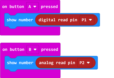
6.1 Reading values from pins
Pin 0 is occupied by the buzzer by default, the jumper should be removed when using this pin.
6.2 Writing values to pins
Pin 0 is occupied by the buzzer by default, the jumper should be removed when using this pin.